1.Dahe CNC Machine Co., Ltd is
the earliest manufacturer for Honing Machine in China. It is the biggest
manufacturer for honing machine with high technical, more model and high
quality. In order to develop CNC Honing Machine, put in to more money and
effort. The [Ningxia CNC Honing Machine Academician Workstation" and [Combined
with Engineering Laboratory of state and local" is set up. It is to undertake
the state major project of high precision honing machine since 2009. The state
major projects are [high precision honing machine", [CNC honing machine for
marine high power diesel engine" and [car connecting" to produce. It is to
undertake the project of producing and research on equipment of high-silicon
aluminum alloy cylinder in 2014. Products are used for automobile, motorcycles,
air-pump, brake disc, cylinder sleeve, gear inside hole, hydraulic parts, kinds
of cylinder etc. It is only one to supply full closed spindle reciprocation
movement, full closed loop of expansion and contraction pressure feed of honing
machine in China.
And also only one reach the level of Germany CNC honing machine
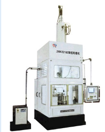
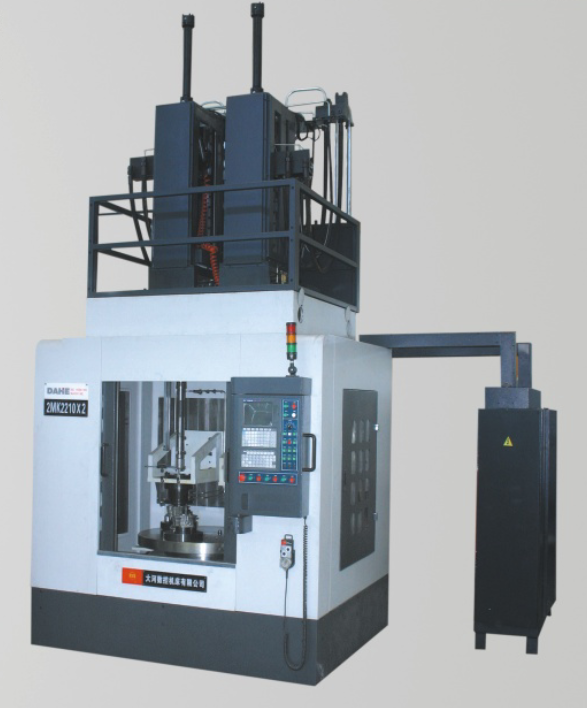
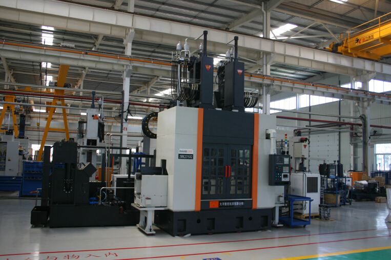
(1)2MK2218x50YS series and 2MK2215X25YS CNC Vertical Honing Machine is a
new kind of CNC honing machine which is designed and produced by our company
according the national science and technology major special project. A new CNC
control system of honing machine spindle reciprocation is designed by us. It is
consist of GSK control system and our special control module and obtained 8
patents of state. The max. spindle
accelerated speed of the machine reach 2.5g.
The control system of the machine can control 5 axis output. The first axis can
control spindle reciprocation move, that is, servo motor drive servo hydraulic
valve, to get high reciprocation move and high accelerated speed, to control high
accuracy of position and short stroke honing; The second axis can control servo
motor to drive spindle rotary with stepless. The first and second axis linkage
can get any honing cross-hatch angle; The third axis can control CNC worktable
to get high accuracy position; Other two axis can control the pressure of rough
and finish honing. This machine is equipped double feeding device,
auto-measuring system to get plateau honing cross hatch. The module design is
selected by the machine. In order to satisfy different customer, we will supply
kinds of collocation from high, middle and low. It is suitable for honing kinds
of automobile cylinder, cylinder sleeve through hole and blind hole which are high
lower than 500 mm.
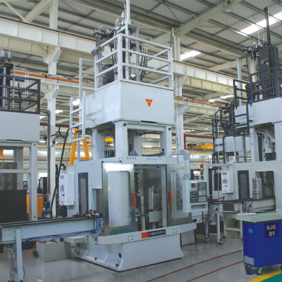
It can be used alone and connecting with production line.
2MK22-Vertical inside CNC honing machine
18X-Max.
honing diameter
50--Max.
honing depth
YS-Hydraulic
servo control spindle reciprocation
G-G: High
collocation; Z: Middle collocation; B: General collocation
A-No letter:
CNC cross worktable; A: Rotary worktable
/1-CNC control
number
Specification Unit 2MK2215x25YSB 2MK2215X25YSG 2MK2218x50YSB 2MK2218x50YSG
Rang of honing
dia. mm Ф50-Ф150 Ф50-Ф150 Ф50-Ф180 Ф50-Ф180
Max. depth of
honing mm 250 250 500 500
Max. spindle
stroke mm 500 500 800 800
Spindle
reciprocation speed m/min 3-25 3-25 3-25 3-25
Spindle rotary
speed r/min 10-600 10-600 10-275 10-275
Type of
worktable mm Ф75 two station
rotary table or 1200x500 CNC cross table (according order)
Spindle rotary
motor power kw 7.5 Servo motor 7.5 Servo motor 11 Servo motor 11 Servo motor
Hydraulic motor
power kw 5.5 5.5 7.7 7.7
High of machine mm 4661 4661 6028 6028
Cover area of
machinem mm 3738x2870 3738x2870 4845x3450 4845x3450
CNC Honing Machine,Vertical CNC Honing Machine,CNC Worktable Honing Machine,Auto CNC Vertical Honing Machine NingXia DaHe Machine Tool (Group) Imp And Exp Co.,Ltd , http://www.nxdhjcmachine.com
Depending on the road, the vehicle and the driver, the individual gears will be subjected to different loads. In order to expand the range of use, the gearbox must have sufficient life for all gears, regardless of road. This means that the gearbox must allow the most unsuitable load at all speeds.
The test cycle delivers such a load, typically a single-stage cycle test time for pitting corrosion of the carburized hardened gear is determined by the Woβhler curve. Indicates a special design strategy: If the damage S is calculated for a certain gearbox, its allowable ultimate load or pressure can be calculated according to the Woβhler curve, which is suitable for gear design. Therefore, an optimal weight gear unit precisely adjusts the gear set and can be designed and developed in a short period of time without having to repeat it.
The Woβhler curve strength values ​​required for life calculations are suitable for testing the gearbox and are continually corrected with new tests. Special life characteristics take into account different materials, qualities, processes, lubricants (additives, viscosity) and various characteristics of the gearbox design as well as the requirements for use (safety).
Modern programs for gear design and recalculation are still an important rule in gear design and recalculation. However, as the requirements have increased, the finite element method has been adopted. Traditional and finite element calculation programs have been combined to form the FE spur gear program series. The finite element (FE) spur calculation program uses the Stiaus program to determine the number of teeth required for the test bench based cycle, allowable load, and individual speed ratios. It helps designers to adopt a comprehensive optimization algorithm and the minimum number of rough requirements for gear parameters. The Stitea program was used for the final design of each gear set and planetary gear train (ie Ravigneaux).
Stifer program and hob, cutting shaft frame steel device seat layer cutting assembly machine tool, grinding wheel is used to determine the semi-finishing and finishing gear cross-section geometry. The Stifa method is used to calculate the tooth shape correction and the space drum tooth geometry. The Stigen program using varying CAD and FE programs implements automatic FE unit generation including boundary conditions and loads. The actual load distribution is achieved using the modulus of elasticity using the Stilas or Stilar program. In such a case, the influence parameter method is no longer applied, and a nonlinear FE program is employed. The calculation results include Fourier analysis of load and deformation distribution and torque error.
Stitea design program with automatic drawing surface map Figure 6 shows that the Stitea design program automatically draws the surface map for easy operation. The program structure is the same as the original version and extended for regular use. In addition to a unit and symbol display, a search card method is employed for input, geometry, tools, etc. of the basic data of each gear set and planetary gear train. The input character set is a chart support. To fully guarantee the user, the additional program is related to selecting each input character set with a footnote. Similar inputs are implemented in a series of possible tests to prevent possible program failures. A number of boundary conditions have to be studied in gear design, which supplements common optimization algorithms with additional support required by Stiaus. Figure 7 shows a basic pre-design to examine the effects of different gear parameters in tabular form.
Gear parameter changes (selected via the pull2down menu) are calculated directly from the addendum correction factor and all new gear parameters are represented in the table in a dialog. This approach has clear operational advantages over processing data batch form programs. Nonlinear Finite Element Program Calculation Figure 15 shows the internal gear and large deflection ring gears and produces a simulation of the contact map offset. A nonlinear finite element program is used for this type of problem. The refinement of the grid is limited due to the extended calculation time.
Therefore, determining contact conditions by polynomial functions (faux functions) and surface bonding is particularly important for such programs. The finite element deviation is due to the large deformation between the precision tooth surface contacts. At the same time, it is necessary to study the characteristics of nonlinear materials related to high load in carburizing and hardening and material tempering.
Calculation of the tilt of the idler in the transmission gear In the example of the "spur gear of the car transmission" described above, the gear is fixed to the shaft. In the case of the idler, the deformation of the housing, the bearing clearance, the shaft have been described. The effect of bending, etc. A slight complicated force flow is applied to the shaft by the idler through the clutch body, the sliding sleeve and the synchronizer body. This system can also be analyzed using the appropriate three-dimensional FE method. All the parts involved, including the contact areas associated with them, are drawn as line drawings, since only durability, stability and friction calculations can be recommended if all parts include contact areas. The results of the detailed geometric line diagrams in the FE model have been accurately and discussed in detail, and are not sufficient for friction without friction.
2.The main model ad spec


Analysis of the current calculation method of gears