Non Woven Manufacturing Machine,Non Woven Fabric Manufacturing Machine,Ultrasonic Non Woven Bag Sealing Machine,Heat Sealing Machine For Non Woven Fabric Changshu Tianli Nonwoven Equipment Co., Ltd. , https://www.tianlimachinery.com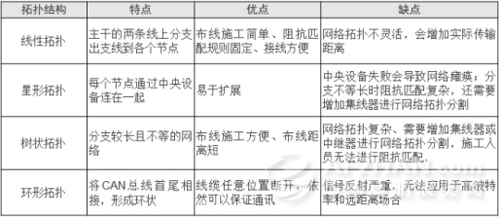

Why CAN bus branch is the most reliable within 0.3 meters?
The linear topology is the most common in the CAN bus cabling specification. If a "T" branch connection in a linear topology is used, the length of the branch can not be greater than 0.3m. What should be done if a longer branch is required?
First, CAN topology classification
CAN (Controller Area Network) belongs to the field of industrial fieldbus. It is a multi-master asynchronous serial communication network that supports distributed control and real-time control. The topology of CAN network mainly includes linear topology, star topology, tree topology and ring topology. The characteristics of the structure of these topologies are shown in Figure 1.
Figure 1 CAN topology features
Second, linear topology wiring
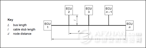
There is a high-speed CAN physical layer specification in IOS-11898-2, in which the recommended CAN network adopts a linear topology in the form of a bus. As shown in Figure 2, the linear topology CAN network uses a single channel (bus) as the transmission medium, and all sites pass The corresponding hardware interface is connected to a common bus. The linear topological impedance matching is relatively simple, and it only needs a suitable termination resistor at both ends of the trunk (typically 120Ω within 2 km).
Figure 2 Linear topology
The linear topology is the most common in the CAN bus cabling specification. The most commonly used linear topology is the “hands- in-hand†connection, as shown in Figure 3.
Figure 3 "Hands-pull" connection
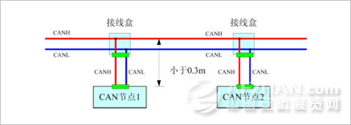
However, in the vast majority of industrial sites and railway locomotives, due to the large number of overall cables, terminal blocks are required to facilitate maintenance. Therefore, the "T" type branch connection is used, as shown in FIG.
Figure 4 "T" type connection
Third, "T" type connection branch constraint
The T-type wiring method has the phenomenon that the impedance is discontinuous due to the accumulation of the branch length and the branch length, and the signal “reflects†at the joint. The amount of reflected signal is determined by the amount of transient impedance change. The greater the amount of change, the more severe the reflection. Negative reflections are generated at the branch, causing the signal level to undershoot. This undershoot may exceed the noise margin and cause false triggering. In order to avoid this, it is hoped that the reflected wave will return to the source as soon as possible, that is, the branch line should be as short as possible.
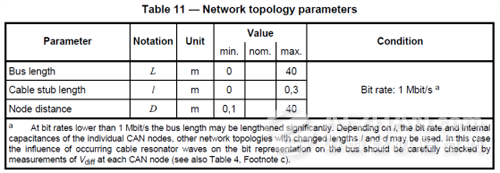
As shown in Figure 5, in IOS-11898-2, the specified branch length must not be greater than 0.3m at 1M baud rate, 1M baud rate is the highest baud rate of CAN, so if other baud rates, the branch length is also Follow the 0.3m specification, you can run steadily.
Figure 5 "T" network topology parameters
Fourth, how to determine the length of the branch
The specification of the branch length in IOS 11898-2 is based on the condition of 1M baud rate. In some cases, it may not be able to achieve short branches. According to different baud rates, the branch length specification may be adjusted appropriately. What is the branch length at different baud rates? Need to analyze the signal quality of the node to evaluate, measure the signal quality of the node at different branch lengths, you can find the appropriate branch length range.
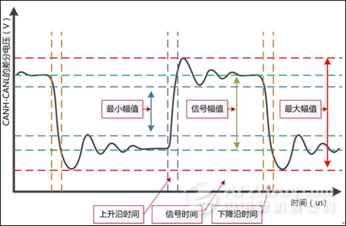
As shown in Figure 6, the signal quality of the evaluation node needs to measure the minimum voltage amplitude, the maximum voltage amplitude, the signal amplitude, the rising edge time of the waveform, the falling edge of the waveform, and the signal time of the node's CAN differential signal. The indicators are specified in ISO 11898-2.
Figure 6 Signal quality parameters
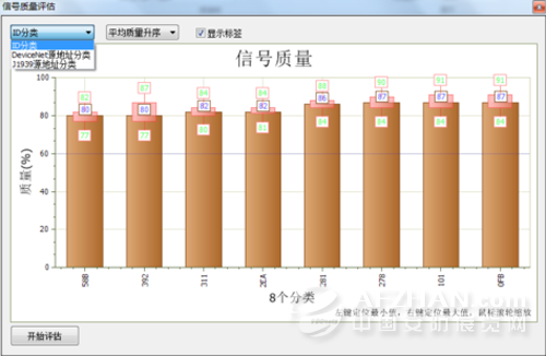
Signal Quality Assessment Without professional tools is obviously a hassle. To quickly evaluate the signal quality of a node, you can use CANScope's signal quality analysis plug-in for one-click analysis. The analysis plug-in automatically evaluates the waveforms sent by each CAN node and comprehensively scores them. The bar graphs are used to visually display the signal quality of each CAN frame ID (as shown in Figure 7) to obtain the signal of each node. Quality, quantitative evaluation of physical layer quality of nodes.
Figure 7 Signal quality histogram