An ultrasonic flow meter (hereinafter referred to as USF) is a meter that measures the volumetric flow rate by detecting the effect of an ultrasonic beam (or ultrasonic pulse) on fluid flow. This article discusses the USF used to measure the liquid flow in closed pipes. In the 1970s, with the development of electronic technology, various models of USF with increasingly improved performance were put into the market. Some people predict that because the USF measurement principle is a combination of two basic quantities, length and time, the amount of derived data is better, and it is possible to establish a traffic benchmark based on this.
The first quarter works
Closed pipes are classified by USF according to the measurement principle: 1 propagation time method; 2 Doppler effect method; 3 beam offset method; 4 correlation method; 5 noise method. This article will discuss the most widely used instrument for the propagation time method and the Doppler effect method.
1.1 Transmission time method
The acoustic wave propagates in the fluid, the propagation speed of the acoustic wave increases in the downstream direction, the direction of the countercurrent decreases, and the same propagation distance has a different propagation time. The flow rate is calculated by using the relationship between the difference in the propagation speed and the flow rate of the fluid to be measured, and the propagation time method is called. According to the measurement of specific parameters, it is divided into time difference method, phase difference method and frequency difference method. The time difference method is used to clarify the working principle.

(1) Flow equation
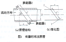
As shown in FIG. 1 , the propagation velocity c of the ultrasonic flowmeter from the transducer 1 to the transducer 2 in the counterflow direction is reduced by the fluid flow velocity Vm as:
 (1)
(1)
Conversely, the propagation velocity of the ultrasonic flow meter from the transducer 2 to the transducer 1 downstream is accelerated by the fluid flow rate as:
 (2)
(2)
Formula (1) minus (2), and transform it,
 (3)
(3)
L - the length of the propagation path of the ultrasonic wave between the transducers, m;
X - the axial component of the propagation path, m;
T12, t21 - travel time from transducer 1 to transducer 2 and from transducer 2 to transducer 1, s;
c - the speed of ultrasonic wave propagation in a stationary fluid, m/s;
Vm - the average flow rate over the channel between the transducers 1 and 2, m/s.
The basic relationship between the time difference method and the frequency difference method and the phase difference method is
 (4)
(4)
 (5)
(5)
Where â–³f - frequency difference;
△ φ - phase difference;
F21, f12 - frequency of propagation of the forward and reverse flow of ultrasonic waves in the fluid;
f - frequency of ultrasound.
It can be seen that the phase difference method is essentially the same as the time difference method, and the frequency and time are sometimes reciprocal relations. There is no essential difference between the three methods. At present, the phase difference method has not been adopted, and the frequency difference method is not many.
(2) Flow equation
The velocity measured and calculated by the time-of-flight method is the mean line velocity on the vocal tract, and the calculated flow rate is the surface mean velocity of the cross-section of the flow. The values ​​of the two are different, and the difference depends on the flow velocity distribution. Therefore, the velocity distribution must be compensated by a certain method. In addition, for the clip-on transducer instrument, the refraction angle must also be compensated by the temperature change in order to accurately measure the flow. Volume flow qv is
 (6)
(6)
Where K - the flow rate distribution correction factor, that is, the ratio of the average channel flow velocity Vm and surface average flow velocity Vm and the average flow velocity v, K = Vm / v;
DN - pipe inner diameter.
K is the flow rate (distribution) correction factor for the mono sound through the center of the pipe (ie, the maximum flow rate of the pipe axis symmetry flow field). The K value of the Reynolds number of the pipeline will change. When the range of the instrument is 10, the K value will change by about 1%. When the range is 100, the K value will change by about 2%. When the flow changes from laminar flow to turbulent flow, the K value changes by about 30%. Therefore, to accurately measure, the K value must be dynamically compensated.
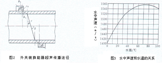
1) In addition to the correction of the flow velocity distribution, the USF of the clip-on transducer USF with clip-on transducer instrument channel angle must also be corrected for changes in the channel angle if necessary. According to Snall's law (7) and Fig. 2, the channel angle θ varies with the speed of sound c in the fluid, and c is a function of the fluid temperature (in the case of water, see Figure 3). θ must be automatically tracked and compensated for the purpose of temperature compensation.
 (7)
(7)
In the formula, the angle of incidence of φ0-ultrasonic in the wedge;
Φ1, φ - Refraction angle of ultrasound in the pipe wall and fluid;
C0, c1, c - wedges, wall, sound velocity of the fluid under test.
The θ angle is not only affected by the sound velocity of the fluid, but also related to the speed of sound in the wedge and the wall material. However, because the sound velocity of a solid material changes by an order of magnitude less than the temperature change of the sound velocity of the liquid, the effect on the accuracy of measurement under negligible temperature changes is negligible. However, in the case of a large temperature variation range (for example, a high and low temperature transducer operating temperature range of -40-200°C), it is necessary to correct large changes in the speed of sound in the wedge and the pipe wall.

2) Flow equations for multi-channel direct transducer transducers The flow equations for direct transducer transducers are not affected by temperature changes in the refraction of the wall material. Gaussian integration or other integral methods are used to calculate the flow for multichannel instruments. FIG. 4 is a schematic model with four channels as an example, and the flow rate calculation formula (8) is shown.
 (8)
(8)
In the formula DN - the average inner diameter of the circular tube or the average inner height of the rectangular tube in the vertical direction of the measurement section and the channel;
S-Gaussian correction factor;
Wi - Gaussian integral weights for each channel;
Li-length of each channel;
Vi - the average flow rate of each channel line;
Θi-channel channel angle;
N-channel number.
2.2 Doppler (effect) method
The Doppler (effect) method USF uses the detection of Doppler shifts at stationary (fixed) points to detect sound waves emitted from a moving source.
(1) Flow equation

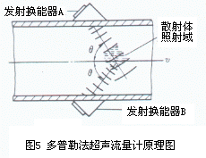
As shown, the ultrasound transducer emits A continuous ultrasonic frequencies fA to the fluid 5, the irradiated region or liquid particles suspended in gas bubbles scatter scatterer, scattering of the ultrasonic Doppler shift frequency fd, the receiving transducer B Received an ultrasonic wave with frequency fB, its value is
 (9)
(9)
In the formula v-scattering body movement speed.
Doppler shift fd is proportional to scatterer flow rate
 (10)
(10)
After the measurement object is determined, the right side of equation (10) is constant except v, and after the transition,
 (11)
(11)
(2) Flow equation
Flow Doppler equation form USF formula (6) the same, except that the measured flow rate is the speed of each scatterer v (Vm in place of the formula), an average flow rate value is not consistent with the carrier liquid conduit; equation the flow velocity distribution in place of the correction coefficient Kd K0, Kd is a coefficient "irradiation field" scatterers in the vicinity of the center of the tube; its value is not available for a large diameter of the scattering body with more or less near the center of the tube is obtained scattered waves The coefficient.
(3) Correction of liquid temperature effect
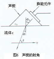
In equation (11), the fluid velocity of sound c is again, and c is a function of temperature. The change in liquid temperature can cause measurement error. Since the temperature change of the sound velocity of the solid affects one order of magnitude less than that of the liquid, that is, the sound velocity c of the fluid in the formula (11) is replaced with the sound velocity c0 of the wedge to reduce the influence when the liquid sound velocity is used. Since cos θ = sin φ is known from FIG. 6 and then the Snell's law sin φ/c = sin φ0/c0, Equation (11) yields Equation (12), where c0/sinφ0 can be considered as a constant.

 (12)
(12)
(4) Influence of Scatterers
In fact, the Doppler shift signal comes from diffusers with different speeds, and the measured relationship between the speed of each diffuser and the average flow rate of the carrier liquid also varies. Other parameters such as the size and size distribution of the scatterers, the non-axial component of the flow velocity of the scatterers, and the degree of attenuation of the scatterers by the scatterers affect the frequency shift signal.
In order to fulfill the ever changing demands of our clients, we have been engaged in offering a quality range of stainless steel accessories. These goods are manufactured using excellent quality material that is sourced from most trusted vendors of market with the aid of our sourcing agents. Post-production, these products are stringently inspected on certain parameters of quality in order to rule out every possibility of defect.
Water Bowl Holder ,Drinking Bowl Holder, Drinking Bowl Bracket,Stainless Steel Metal Steel Flat
Ningbo New Glory International Trading Co.,Ltd , https://www.stock-farming.com