Permanent Synchronous Motor,Permanently Excited Synchronous Motor,Three Phase Synchronous Motor,Permanent Magnet Synchronous Electric Motor Jiangsu Xibang Hydraulic Machinery Co.,Ltd , https://www.xibanghydraulic.com
Features
With a strong magnet and spring force, the valves are tough against contamination and thus ensure a stable operation.
Solenoids
Solenoid Connectors (DIN connector)
The solenoid connectors are conform to the international standard ISO 4400 (Fluid power systems and components-Three-pin electrical plug connectors Characteristics and requirements)
AC Solenoids
50 to 60 Hz common service solenoids do not require rewiring when the applied frequency is changed.
DC Solenoids (Reputable K-series)
These DC solenoids have surge absorbers for K-series functions. The three advantages of them are as mentioned below:
1. Since surge voltage can be controlled to a very low figure, electric control devices, such as a computer, can be used without any interference like noise.
2. There being no spark between contacts, the life of the relay becomes longer.
3. Time lag for spool return after de-energisation of the solenoid is very short.
Specifications
Valve Type
Model
Numbers
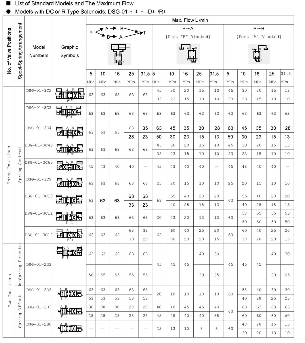
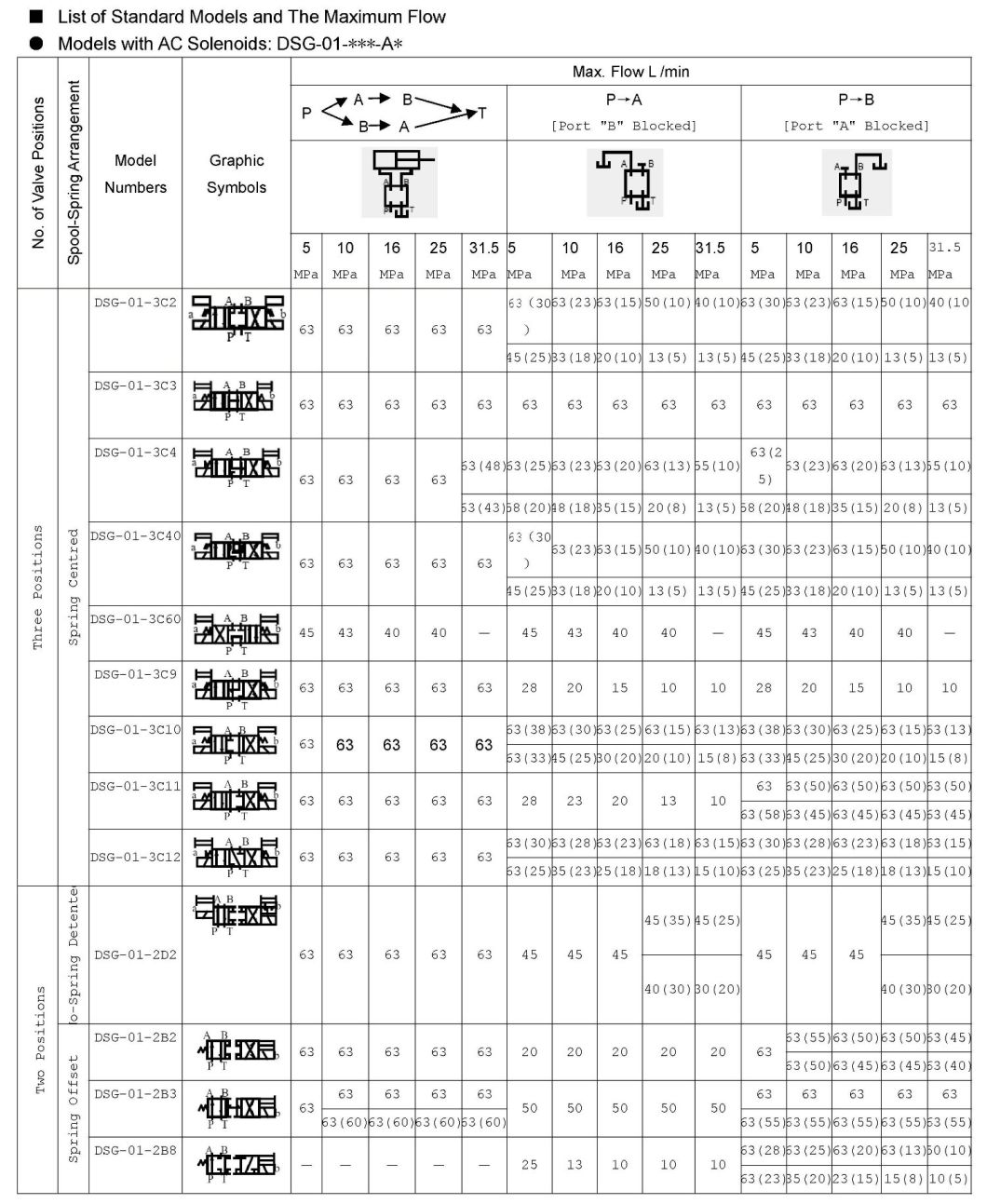
Max. Flow
L /min
(U.S.GPM)
Max. Operating
Pressure
MPa (PSI)
Max. T-Line
Back Pres.
MPa (PSI)
Max. Changeover
Frequency
min-1 (Cycles/Min)
Approx. Mass
(kg)
Standard
Type
DSG-01-3C∗-∗-50
63 (16.6)
31.5 (4570)
{Spool Type 60 Only
25 (3630)}
16 (2320)
300
{R Type Sol. Only}
120
2.2
DSG-01-2D2-∗-50
2.2
DSG-01-2B∗-∗-50
1.6
Shock less
Type
S-DSG-01-3C∗-∗-50
40 (10.6)
16 (2320)
16 (2320)
120
2.2
S-DSG-01-2B2-∗-50
1.6
Valve Type
Electric source
Coil
Type
Frequency
(Hz)
Voltage (V)
Current & Power at Rated Voltage
Source Rating
Serviceable Range
Inrush (A)
Holding (A)
Power (W)
Standard
Type
Â
Shock less
Type
AC
A100
50
100
80 - 110
2.42
0.51
―
60
100
90 - 120
2.14
0.37
110
2.35
0.44
A120
50
120
96 - 132
2.02
0.42
60
108 - 144
1.78
0.31
A200
50
200
160 - 220
1.21
0.25
60
200
180 - 240
1.07
0.19
220
1.18
0.22
A240
50
240
192 - 264
1.01
0.21
60
216 - 288
0.89
0.15
DC
(K Series)
D12
―
12
10.8 - 13.2
―
2.45
29
D24
24
21.6 - 26.4
1.23
D48
48
43.2 - 52.8
0.61
AC→DC    Rectified (R)
R100
50/60
100
90 - 110
―
0.33
29
R200
200
180 - 220
0.16
F-
S-
DSG
-01
-2
B
2
Special
Seals
Shock less
Type
Series
Number
Valve
Size
Number
of Valve
Positions
Spool-
Spring
Arrangement
Spool
Type
F;
For Phosphate
Ester Type
Fluids
(Omit if not
Required)
None:
Standard
Type
DSG:
Solenoid
Operated
Directional
Valve
01
3
C:
Spring
Centered
2,3,4,
40,60,9
10,12
2
D:
No-Spring
Detened
2
B:
Spring
Offset
2,
3,
8
S:
Shock
less
Type
3
C:
Spring
Centered
2
4
2
B:
Spring
Offset
2
A
-D24
-C
-N
-50
-L
Special Two
Position Valve
(Omit if not Required)
Coil
Type
Manual
Override
Electrical
Conduit
Connection
Design
Number
Models with Reverse Mtg. of Solenoid
(Omit if not required)
―
AC:
A100Â A120
A200Â A240
DC:
D12 D24 D48
R:
(AC→DC)
R100 R200
None:
Manual
Override
Pin
C :
Push
Button
and
Lock Nut
(Option)
None:
Terminal
Box Type
Â
N:
Plug-in
Connector
Type
N1:
Plug-in
Connector
Type with
Indicator Light
(Option)
50
―
―
―
A
B
L
―
DC:
D12 D24 D48
R:
(AC→DC)
R100 R200
―
―
L


Â

Features
With a strong magnet and spring force, the valves are tough against contamination and thus ensure a stable operation.
Solenoids
Solenoid Connectors (DIN connector)
The solenoid connectors are conform to the international standard ISO 4400 (Fluid power systems and components-Three-pin electrical plug connectors Characteristics and requirements)
AC Solenoids
50 to 60 Hz common service solenoids do not require rewiring when the applied frequency is changed.
DC Solenoids (Reputable K-series)
These DC solenoids have surge absorbers for K-series functions. The three advantages of them are as mentioned below:
1. Since surge voltage can be controlled to a very low figure, electric control devices, such as a computer, can be used without any interference like noise.
2. There being no spark between contacts, the life of the relay becomes longer.
3. Time lag for spool return after de-energisation of the solenoid is very short.
Specifications
Valve Type
Model
Numbers
Max. Flow
L /min
(U.S.GPM)
Max. Operating
Pressure
MPa (PSI)
Max. T-Line
Back Pres.
MPa (PSI)
Max. Changeover
Frequency
min-1 (Cycles/Min)
Approx. Mass
(kg)
Standard
Type
DSG-01-3C∗-∗-50
63 (16.6)
31.5 (4570)
{Spool Type 60 Only
25 (3630)}
16 (2320)
300
{R Type Sol. Only}
120
2.2
DSG-01-2D2-∗-50
2.2
DSG-01-2B∗-∗-50
1.6
Shock less
Type
S-DSG-01-3C∗-∗-50
40 (10.6)
16 (2320)
16 (2320)
120
2.2
S-DSG-01-2B2-∗-50
1.6
Valve Type
Electric source
Coil
Type
Frequency
(Hz)
Voltage (V)
Current & Power at Rated Voltage
Source Rating
Serviceable Range
Inrush (A)
Holding (A)
Power (W)
Standard
Type
Â
Shock less
Type
AC
A100
50
100
80 - 110
2.42
0.51
―
60
100
90 - 120
2.14
0.37
110
2.35
0.44
A120
50
120
96 - 132
2.02
0.42
60
108 - 144
1.78
0.31
A200
50
200
160 - 220
1.21
0.25
60
200
180 - 240
1.07
0.19
220
1.18
0.22
Synchronous Motor
Solenoid Operated Directional Valves, DSG-01 Series
Model NO.: DSG-01, Terminal Box Type
Power Supply: AC and DC
Usage: Direction Control
Standard: GB
Application: Industrial Usage
Max.Pressure: 31.5MPa
Max.Flow: 63L
Trademark: Seric
Transport Package: Carton Box/Wooden Case
Specification: 2b2,2b3,2b4,2b8,3c2,3c3,3c4,3c60,3c9,3c10,3c12,2d2
Origin: Guangzhou
HS Code: 8413910000
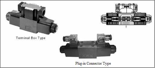
These are epoch-making solenoid operated directional valves of high pressure, high flow which have been developed incorporating a unique design concept into every part of the valve including the solenoid. With wet type solenoids, these valves ensure the low noise and the long life, moreover, ensure no leakage of oil outside of the valve.
Stable OperationModel Number Designation
Â
These are epoch-making solenoid operated directional valves of high pressure, high flow which have been developed incorporating a unique design concept into every part of the valve including the solenoid. With wet type solenoids, these valves ensure the low noise and the long life, moreover, ensure no leakage of oil outside of the valve.
Stable Operation