Hand Folding Machine,Sheet Metal Plate Folding Machine,Manual Sheet Metal Plate Folder,Medium-Sized Hand Folding Machine HT-Metalforming Equipment Manufacturing Co.,Ltd , https://www.htmetalforming.com


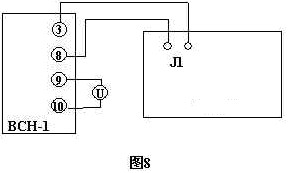
D, the entire group of volt-ampere characteristics test, the wiring as shown below
Single phase relay protection tester use method
SDY805 single-phase relay protection tester can be used at the same time refer to the Ministry of Water Resources and Electricity Production Division, "protection relay inspection" water conservancy press.
1. Measurement: Can be used as a separate voltage and current source, but at the same time pay attention to the output power to avoid damage to the instrument (can not be used to start the motor); specific operation according to "output power operation".
2. Over-range, under-range: Measure the action value, return value, contact action time and return coefficient (including voltage and current relays) of various relays.
Over-range refers to the relay with the relay contact closed as the action value. Under-range refers to the relay with the relay contact separated as the action value. The specific operation steps are as follows:
Measurement of the relay's action value, return value, and return coefficient:
Output the power according to “Output Power Operation†above, and select T3 to ○. Turn the synchronization switch ON, slowly adjust the T4 knob until the relay starts, (can be judged by the indicator), X1 shows its action value, and record. After continuing to adjust T4 to the relay rating, then slowly adjust T4 until the relay returns, X1 displays its return value, and record. Divide the return value by the action value multiplied by 100% to calculate the return coefficient.
Relay time measurement:
Press “Output Power Operation†to output power and select T3 to ○. Turn the sync switch ON and slowly adjust the T4 knob until the relay starts and adjusts to the rated value. Select T3 to the contact state of the relay and measure the relay time (X2 display time) by switching the synchronous switch. Pay attention to the need to clear the millisecond meter before measuring time, and the closing switch is in the open state. The correspondence between the synchronous switch and the contact state is:
The normally open contact energizes and the normally closed contact energizes and delays the open state. The synchronous switch is turned from the OFF state to the ON state.
Normally open contact power-off delay open and normally closed contact power-off delay close state, synchronous switch turns from ON state to OFF state.
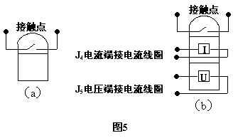
The contact wiring is as follows:
3. The time relay measurement is the same as the above method.
4. Reclosing (taking DH-3 reclosing as an example)
Connect the wire as shown in the figure above, connect (3) (4) to J5 black (negative), (17) connect to J5 red (positive)
Note: When using the ZJ3 contact to stop the millimeter, please pay attention to disconnect the connection of ZJ3 to the (12) pin, separate the ZJ3 contact (see “Protection Relay Test†on page 352), turn T1 to IDC0 ~ 20A file, dial switch S2, adjust T4 to the relay current rating, dial switch S2, turn the T2 knob to the relay voltage rating. Select T3 to I (that is, the contact state of relay ZJ3). Then switch the S2 and S3 switches at the same time. After charging for 15 to 25 seconds, the charging time can be read on the millimeter meter. Press the millisecond meter reset button and press the “close†button to measure the reclosing time. X2 shows the reclosing time.
5. Intermediate relay
As shown in the figure, (a) Operate with the same overrange, underrange relay, measurement action value, return value, action time, and return time.
(b) Select the current holding relay by adjusting T2 to the voltage rating of the relay, and turn on the switches S2 and S3 so that the voltage coil of the relay is added to the rated voltage relay. After the action of the relay, adjust T4 to make J4 current to the rated value, and then disconnect the voltage ( The S3 switch is turned down), the current of the protection coil (T4) is adjusted, and the minimum current that can be held by the relay is the minimum retention value of the relay. Its operation time and return time are performed according to the above (2, 3).
6. Differential Relay: Take BCH-1 Differential Relay as an Example
According to the requirements of the regulations (see “Protection Relay Inspection†page P178), the fourth, ninth and tenth experiments can be done without external equipment, and the sixth item can be done in the case of an external voltage regulator and a riser. Experiments, others are outside the scope of this instrument.
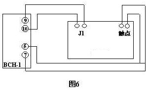
A. Check the operating voltage of the actuator, the operating current and the return current. Wiring as shown below.
Open the continuous piece between the (10) and (11) terminals, measure the operating current according to the method of the current relay, and return the current, then raise the current IAC to the current value just measured, and record the voltage value at this time (X1 voltage Display readout), also can use the multimeter to measure the voltage value of both ends of J2.
B. Start ampoule inspection without braking
This item is not an ordinary periodic inspection item. Put all 20 turns of the WC working winding, connect the shorting piece of (10)(11), and add AC current from (3)(8). The contact action signal is from 5) (7) access to the contacts, according to the method of current relay inspection.
C. Braking characteristics experiment
For regular inspections, only the ampere measurement values ​​of 0° and 280 amps for brake ampoules are measured.
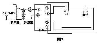
Connect the wiring according to the figure above, disconnect the connecting piece of the (4) (6) terminal, take 39 turns of the operating circuit, take 14 turns of the brake circuit, and use the same 220V power supply for the voltage regulator (more than 5KVA). The braking current is increased to the required amperage and the operating current is made according to the method of the AC relay. If the motion safety amp is completely wrong, it may be that the phase angle of the braking current and the operating current is 180 degrees. It is better to reverse the braking current. If the instrument uses one of the three phases, the voltage regulator uses another. In phase, the phase angle of 60° can be obtained by changing the phase and inverting the riser. For external phase shifters, all phase angles of 0°, 30°, 60°, and 90° are also available.
In the alternating current in the working winding (3)(8), the voltage of the actuator is read from (9)(10) by a meter, selects T1 to IAC, and ramps up to the desired number of amps, reading 1 The voltage value of the actuator terminal is executed at times of 2, 5, and 5 times. For details, see page P183 of the book "Protection Relay Inspection."
E. Operation and safety inspection at setting position
The method is the same as the alternating current relay. For details, see item (2) in item 5 of this manual.