Y83 series block making machines are industrial machines designed to make maximum use of metal swarf such as cast iron, aluminum, copper, steel, brass, zinc, bronze, titanium and magnesium, they are also suitable for other machining scraps by pressing them into briquettes. It results in economic benefits for companies that generate the swarf, companies that recycle metal scraps, and for foundries that process the scraps. Also there is environmental benefits resulting from the briquetting process.
Metal Block Making Machine, Scraps Block Making Machine, Aluminum Block Making Machine, Steel Block Making Machine, Chips Block Making Machine Jiangyin Metallurgy Hydraulic Machinery Factory , https://www.eco-metalsrecycling.com
HIC-1000 distributed control system configuration shown in Figure 1. The system uses the domestic "893" intelligent data measurement and control front-end, and the I/O station can be directly placed on the site according to the need, realizing the physical dispersion of the system. 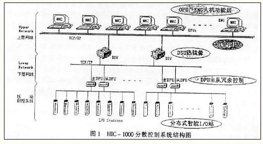
First, the controller HIC-1000 distributed control system uses PID and FUZZY (fuzzy) two controllers. Different controllers are used for different process objects.
(1) PID controller The PID controller is a linear controller suitable for linear, steady, and uncoupled (weakly coupled) systems. Calculated as follows:
Ud=a·(Ud(n-1)+b·(e(n)-e(n-1)))
a=Td/(Kd·TK+Td), b=KP·Kd
â–³Up(n)=Kp(e(n)-e(n-1))
Ud = Ud (n) - Ud (n - 1)
△Ui=KP·TK·e(n)/Ti
△Un=ΔUP(n)+ΔUi(n)+AUd(n)
U(n)=U(n-1)+ΔU(n)
In the formula:
KP: Proportional amplification factor Ti: Integral time constant Td: Derivative time constant K2: Integral separation factor TK: Control period Step: Step length limit Sc: Dead zone Kd: Differential amplification factor e: Deviation within sampling period e—1: Previous step Deviation within sampling period Ud-1: Differential value during the previous control cycle (2) Fuzzy controller (FUZZYCONTROLER)
Fuzzy control is a typical representative of artificial intelligence control. It imitates the logic of human thinking and summarizes, abstracts, reasoning, quantifies, and implements effective control over the operating discipline of the controlled object (often without an exact mathematical model). The basis of fuzzy control is fuzzy mathematics. Using fuzzy mathematics reasoning theory, the membership function database is built off-line and various complex process objects are simplified. This process requires the designer to have a full understanding of the controlled object. It is a direct operator and has rich experience in order to sum up the rules and establish a database of membership functions. When running online, using computer's high-speed, large-capacity performance, through the inference, quantitative calculations to get a specific amount of control. Fuzzy control is a nonlinear controller suitable for time-varying, nonlinear, and strongly coupled systems. The fuzzy controller block diagram is as follows:
In the picture:
K1, k2: Scale factor k3 for scaling (fuzzy quantization): Scale factor for scale conversion (clear) r: Reference input e: Deviation between actual input and reference input e': Variation in deviation u: Cleared The precise control FUZZY controller is mainly composed of four parts: 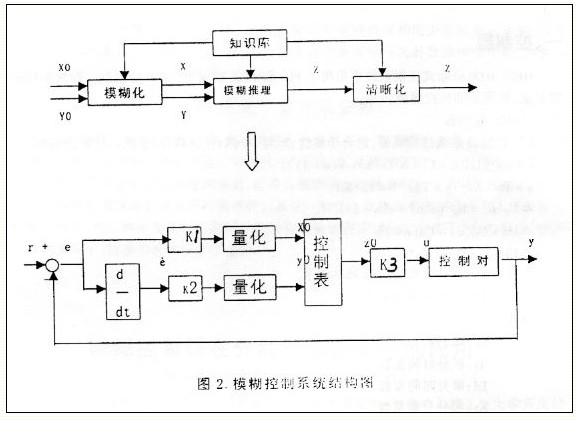
(1) Fuzzification The function of this part is to process the precise amount of input into the input required by the fuzzy controller. The processed input is scaled, transformed to its own domain, then blurred and represented by the corresponding fuzzy set. The input includes external reference input, system output, or status.
(2) Knowledge base Knowledge base is usually composed of database and fuzzy control rule base. The database includes membership functions of each linguistic variable, scale conversion factors, and the number of levels of the fuzzy space. The rule base includes a series of control rules expressed in fuzzy linguistic variables. They reflect the actual control experience and knowledge.
(3) Fuzzy reasoning Fuzzy reasoning is the core of FUZZY controller. The fuzzy reasoning process is based on the implication relations and inference rules in fuzzy logic.
(4) The function of clearness and clearness is to transform the fuzzy control quantity into a clear quantity expressed in the scope of the discourse by clearing the fuzzy control quantity, and finally change the clear measure quantity to the actual control quantity.
Second, the water supply control loop The feedwater control loop can control the water level of the drum, and can also control the flow of the feedwater. It can be realized by controlling the main water supply valve or the auxiliary water supply valve. Both of them adopt the typical double-loop PID control, and the inner loop controls the water supply flow, and the outer loop control. Bubble water level, the control block diagram shown in Figure 3, so there are four groups of PID controller parameters, the main water level and the main water supply gate for the main water supply automatic control of the two; auxiliary water level and auxiliary water supply door for two groups Automatic control of the auxiliary water supply door. In addition, it has PID correction parameters, and cooperates with the PID controller to realize the conversion of various control states and the adjustment of control strategies. 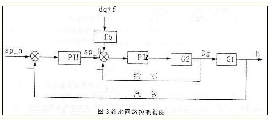
Symbol Description:
Sp_h: Drum water level given value;
h: drum level;
sp_Dgs: inner ring water supply flow given;
Dgs: water supply flow;
Dq: Main steam flow;
Fb0: Feedwater flow rate feed forward coefficient;
Fbl: at steady state, fbl:Dgs-Dq;
P11: Main regulator;
PI2: secondary regulator;
Gl: water gate characteristic function;
G2: drum characteristic function;
Third, the desuperheated water control loop (1) process flow chart The first and second superheated steam temperature control system of each process flow shown in Figure 4:
Θ0: Desuperheater temperature.
Θ2: Temperature after desuperheater.
Θ1: post-superheat temperature.
DJWS: Desuperheated water flow.
(2) Control block diagram The desuperheated water control can control the steam temperature at the desuperheater outlet, and can also control the leading temperature, using double-loop PID control, and control block diagram. 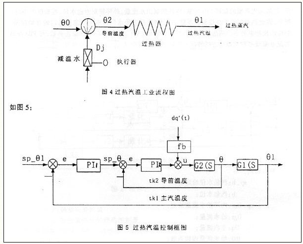
Sp_θ1: Superheater outlet temperature setpoint.
E1: The main regulator is misaligned.
Θl: Superheater outlet steam temperature.
PI1: Main regulator.
U1: main regulator control output, given as inner ring,
TK1: Main regulator control cycle.
G1(S): Main loop transfer function.
Sp_θ2: Superheater inlet temperature setpoint.
E2: The PI2 regulator is misaligned.
Θ2: Superheater inlet steam temperature.
PI2: Regulator.
U2: PI2 regulator control output.
TK2: PI2 regulator control period, TK2 = 3 - 4TK1.
G2(S): Desuperheater transfer function.
(3) Control scheme The desuperheated water control includes a total of three control loops of the first-stage cold section A outlet temperature of the steam header, the first-stage cold section B outlet temperature of the steam header and the main steam temperature, and each loop controls a minus. Warm water gate (respectively a first floor door, first floor door, and second floor door). Both use double closed loop PID control scheme. The inner ring is quickly adjusted: the outer ring eliminates the steady-state error and controls the superheated steam temperature.
For the effect of lifting load on the main steam temperature, the “load change†feedforward of the main steam temperature is introduced, which directly acts on the outlet of the inner ring regulator. The feedforward coefficient is taken as multi-stage value and corresponds to different types of external disturbances. The adoption of this technology will have better effect on the superheated steam temperature control of the peaking unit (boiler).
Fourth, the suction control loop (1) control program negative pressure control difficulties lies in the following two aspects:
(a) At steady state, changes in coal quality, baffle characteristics, and other external disturbances cause system instability. As time passes, the system's characteristic function will produce large changes (especially after major repairs). It is prone to turbulence, resulting in instability of the furnace negative pressure.
(b) The boiler leakage coefficient gradually increases over time, resulting in increased oxygen content in the flue gas. If the negative pressure is not stable (the opening of the air door does not change), the oxygen content of the flue gas changes, which leads to the positive feedback action of the sending air control system, and the system is divergence and unstable.
(c) The start-stop of the pulverizing system and the system's "downwind" operation may cause large negative pressure fluctuations in the furnace. This process requires fast tracking and adjustment.
Therefore, HIC-1000 decentralized control system in the furnace negative pressure using PID and FUZZY combined control. 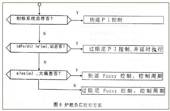
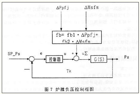
e: Main regulator deviation.
Ps: furnace negative pressure.
Controller: Select the corresponding controller according to the control strategy.
u: The main regulator controls the output.
U∑: The total control amount is output to the wind actuator.
Tk: main regulator control period, Tkl = 1 ~ 2 seconds.
G(s): Main loop transfer function.
Fb: feedforward increment.
Fbl: outlet pressure feed forward coefficient fb2: air feed door opening feed forward coefficient:
â–³Ppfj: discharge pressure increase of the powder discharger.
â–³ Msfm: air supply door opening increment.
(3) Fuzzy control parameter table:
In order to save memory, the method of symmetry storage is adopted for Fuzzy and the table, ie, the deviation is divided into positive and negative symmetry settings, and the sub-matrix of the negative deviation part and the sub-matrix of the positive deviation part are transposed symmetrically and stored in the same one. The unit can reduce the amount of data in the Fuzzy table by half, which is beneficial to speeding up the operation. For fast and overdamped fuzzy control schemes, changing the weighting factor and the fuzzy control period can be used, and both control modes share the same matrix table.
V. Air supply control loop (1) Difficulty of control strategy air supply control is as follows:
(a) The leakage coefficient of domestic boilers has become more and more serious with the passage of time, especially small and medium-sized units. Leakage caused by the door opening degree of the amount of change in the amount of smoke oxygen was a serious nonlinear relationship, even the inverse relationship curve, severe time-varying characteristics. Changes in negative pressure lead to changes in the amount of air leakage, eventually resulting in changes in the amount of oxygen in the flue gas.
(b) Domestic cerium oxide is not stable, its service life is only half a year, and the oxygen measurement error is large, which cannot truly reflect the combustion efficiency of the boiler. Therefore, rely on the oxygen method to control the air supply. Can not achieve the best economic combustion effect, often lead to the wind divergence control system, combustion is not enough.
(c) The wing air measuring device has a large error, which affects the accuracy of the control.
To sum up, abandon the traditional control strategy of “controlled air supply based on oxygen amount†and adopt the “wind/coal ratio β self-optimizing†control scheme. According to the boiler load and combustion status, use fuzzy inference logic to search online for optimal air supply. The pressure value controls the supply air volume indirectly by controlling the supply air pressure to achieve the best economical combustion.
(2) Wind/coal ratio online optimization control scheme The optimal air supply pressure calculation process is shown in Figure 8 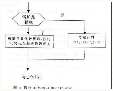
Among the fixed value calculation formula:
f(Dq)={(psfH-psfL)/(DqH-DqL)}(Dq-DqL)+psfL
In the formula:
psfH, psfL: upper and lower limits of air supply pressure
DqH, DqL: upper and lower boiler load,
△Psf: Offset, the furnace can be determined by the OPU The basic principle of the wind/coal ratio β on-line self-optimization is to make the feed speed of the feedstuff constant and the suction input automatic, according to this step under relatively stable load conditions. There is a change in the air supply pressure of the sampling period and the control of the opening of the air supply door. Calculate DQ=Dq+Co*dPb(t)/dt in the following sampling periods.
Among them, DQ refers to the amount of heat absorbed by the boiler feed water per unit of evaporation, and the unit is T/h; Dq is the steam flow, and the unit is T/h; Co is the heat storage coefficient of the steam drum. If ΔDQ>0, it indicates that the current search direction is correct, and the search can continue in this direction; otherwise, the search should be reversed. The determination of the search step length is given by the fuzzy matrix. The beta self-seeking process is shown in Figure 9. The starting point of fuzzy self-optimizing exploration begins with f(Dq) + ΔPsf (formula of air supply pressure calculation). 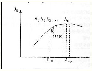
Where A1, A2, ..., Ai, ..., A. For the search process of the guiding process, the artificial final convergence point is also the optimum wind-to-coal ratio, and Stepi is the search step length at the i-th step. If the steam flow fluctuation is found to be large during the guide search process, the search is stopped, and the control for maintaining the set pressure of the supply air pressure is switched to, and the powder is also transferred to the automatic control. The beta homing search period is 2 hours. The search time is 10---15min.
The supply air pressure constant value calculation control is an approximate optimal control. The supply pressure control curve Sp_Psfy1=f1(Dq)B is a linear function; and the supply pressure curve controlled by the self-search wind/coal ratio is Sp_psfy1= F2(Dq) is a nonlinear function and is the best control method. In the control mode, the main steam flow differential is introduced as the feedforward amount to realize the fast tracking of the load by the air supply control.
(3) Control block diagram 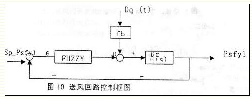
In the picture:
e: Air supply pressure deviation u: Control output of FUZZY controller, valve opening G(s): Air supply pressure - The transfer function of the air supply door fb: The feed forward coefficient of the main air flow to the air supply control Dq(t) : The main gas flow differential U Σ é€ é€ é€ Î£ Σ Σ Σ Σ Σ Σ Σ Σ Σ Σ Σ Σ Σ Σ Σ ps ps ps ps ps ps ps ps ps ps ps ps ps ps ps ps ps ps ps ps ps ps ps ps ps ps ps ps ps ps ps ps ps ps ps ps ps. Also related to air leakage, it can be expressed as Sp_Psfy1=f(Dq(t),γ,σ)
Among them, D is the combustion value of coal, and the outlet is the leakage coefficient of the boiler.
Sp_Psfy1 is a time-varying, non-linear, non-stationary coefficient. The air supply and induced wind control subsystem caused by it is a time-varying, nonlinear, non-stationary system.
Sixth, powder control loop (1) Control strategy and block diagram When the single furnace is running, the main steam pressure is controlled. When there are two or more boilers running in parallel, the main steam pressure can be controlled, and the pressure of the main pipe can also be controlled. The block diagram is shown in Figure 11.
Symbol Description:
Controller 1: Master pressure regulator to control the pressure of the mother tube. The output is all boiler total load reference values ​​running in parallel on the same parent pipe, SP_Dq: This value reflects the load necessary to balance the parent pressure.
Controller 2: Each boiler load regulator controls the corresponding boiler output. The output is the feed speed of the corresponding boiler. This value reflects the speed of the powder feeder necessary to balance the boiler load reference.
A1, a2, a3: 1#-3# boiler load distribution coefficient. The control system uses a1, a2, a3 to assign the total load setpoint SP_Dq to each boiler. Each furnace controls its own output according to its own load, and the load distribution coefficient satisfies:
∑ai=1i=1,2...num_bolier
SP2: Each boiler load is given. SP2(i) = SP_Dq·a(i).
Dq: Main steam flow of the boiler.
Fbpb: drum pressure feed forward coefficient fbdq: main steam flow rate feedforward coefficient â–³pb: steam drum pressure increment.
â–³Dq: main steam flow increment.
Pm: Master pressure.
TK: Control cycle.
G1(S): Thermal system transfer function.
G2(S): Boiler combustion system transfer function.
(2) Control program block diagram In order to achieve steady state and dynamic index, it is necessary to distinguish between the state of the combustion system in the control process - steady state and transient state. The dynamics caused by internal disturbances and external disturbances use different controllers, respectively, as shown in Figure 12. When the main pipe pressure/main steam pressure deviation is large, the system is in a dynamic process and a fast PI controller is used; otherwise, a large damping PI controller is used. The inner ring is a follow-up system with respect to the outer ring. 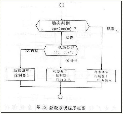
(3) Special handling under large load disturbances For small and medium-sized generating units, because the turbine is not on the “electrical adjustment†device, the turbine and the boiler cannot achieve coordinated control. However, the actual operation of the site requires that the load of the boiler be quickly followed by the demand of the turbine load and the external network load of the parent pipe, which leads to a change in the speed range of the powder machine, and the speed is fast. When the steam turbine quickly dumps load due to faults and other reasons, it is difficult for the regulating system to keep up. For this reason, the automatic switch control technology of the powder feeder is adopted. The basic idea is: when the turbine quickly dumps load and the external network load suddenly drops, Adjustment system according to the size of the load changes, the speed of the main steam pressure rise, emergency stop 1-2 sets to the powder machine, so that the fuel volume quickly decreased, while also stabilizing the transfer speed of other powder machine, not due to all the powder machine speed A rapid drop causes fire. The switching logic for the powder machine is automatically completed in the control program.
The use of automatic switching technology to the powder machine enables the automatic adjustment of the boiler load to a range of 60% to 110%, which is the true indicator of continuous automatic operation through the combustion system "72h". 
Seventh, the coal mill controls the coal mill control content including the coal mill inlet negative pressure and the pulverizer exit temperature. The two coal mills are independently controlled. The pulverizer population negative pressure uses the FUZZY controller, and introduces the pulverizer outlet temperature control door opening (the coal mill population hot air door opening) as its. The feed-forward of the population negative pressure regulation gate; the outlet temperature of the coal mill adopts a PID controller, which is a simple single closed-loop control system. Coal mill control block diagram shown in Figure 13,14.
8. The control of the powder discharger for the powder discharger includes the outlet pressure of the powder discharger and the outlet temperature of the powder discharger. The two powder dischargers are independently controlled. The outlet pressure of the pulverizer is FUZZY controller, and the opening of the pulverizing system exhaust valve, the opening of the recirculation door, the opening of the powder outlet temperature adjustment door (population cooling fan door) are introduced as the outlet pressure adjustment door ( Feeder population temperature door) feed forward; exhaust outlet temperature using PID controller, a simple single closed-loop control system. The dumper control block diagram shown in Figure 15,16.
Application of Fuzzy Controller in Distributed Control System
At the end of last year, China Aerospace Industry Corporation held a technical appraisal meeting in Tiefa, Liaoning Province, for the HIC-1000 developed by Harbin Institute of Technology on the No. 2 boiler (130t/h) of the low calorific value coal-fired thermal power plant of the Tiefa Mining Bureau. The decentralized control system was technically appraised. The most important feature of this system is that widely used advanced control technologies such as fuzzy control are injected into the DCS system and successfully applied to some large-delay, nonlinear, control parameter coupling and other complex control systems in low-thermal-value coal-fired boilers and master control systems. The control system is briefly introduced here for the reader's reference. Symbol Description: Symbol Description SP_Ps: Furnace negative pressure setpoint.
Next Article
Mini van advantages